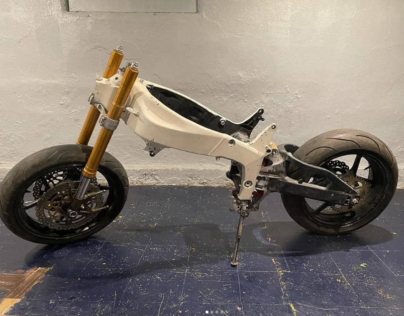
Our team set out to convert a 2005 Kawasaki Ninja ZX-6R into a high-performance electric superbike, targeting a top speed of 100+ mph for the AHRMA Formula Lightning competition.
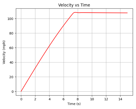
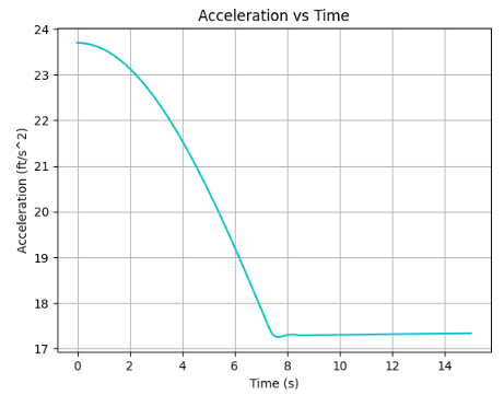
I built a Python script to model the forces acting on the bike (drag, rolling resistance, and wheel force), solving a differential equation to generate velocity and acceleration curves over time. By simulating different gear ratios and accounting for tire friction and slip ratio, I determined an ideal output torque of ~575 Nm, requiring a 5.2:1 reduction from our ZF75-7 motor's (50 kW, 3 phase AC) 110 Nm peak output.
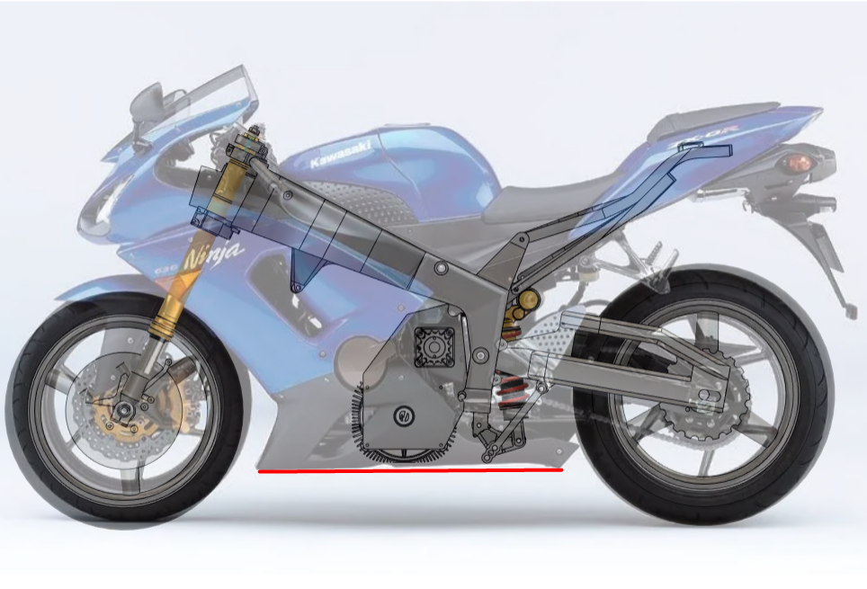
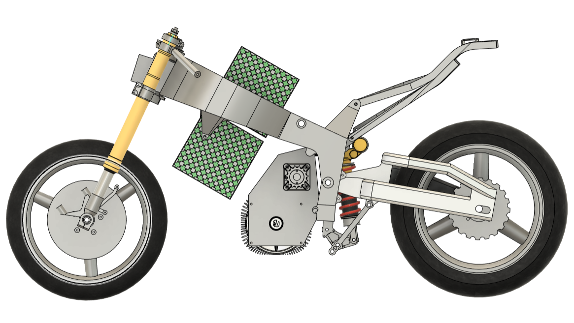
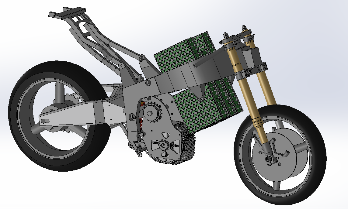
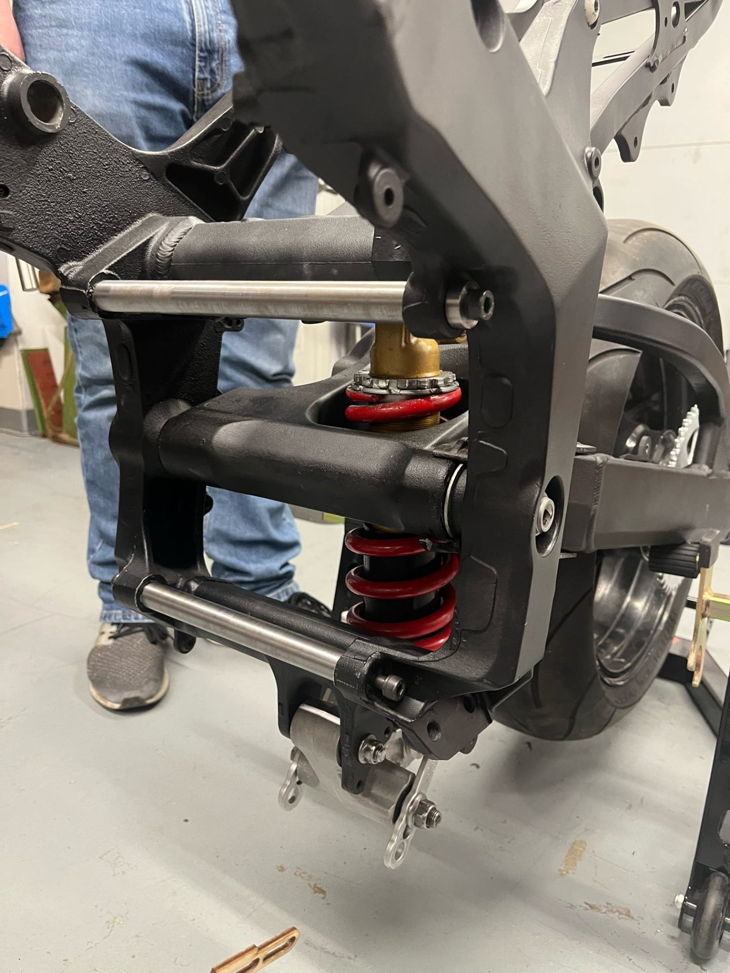
A single-stage reduction wasn't viable at 5.2:1, so I designed a two-stage system with an 18:10 ratio from motor to jackshaft and a 43:15 ratio from jackshaft to wheel, landing at a 5.16:1 reduction. The biggest challenge was packaging: the motor sits as low as possible above the bottom fairing, freeing space for the battery and BMS, while the jackshaft position is parameterized relative to the suspension pivot for easy anti-squat tuning.
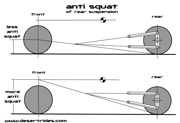
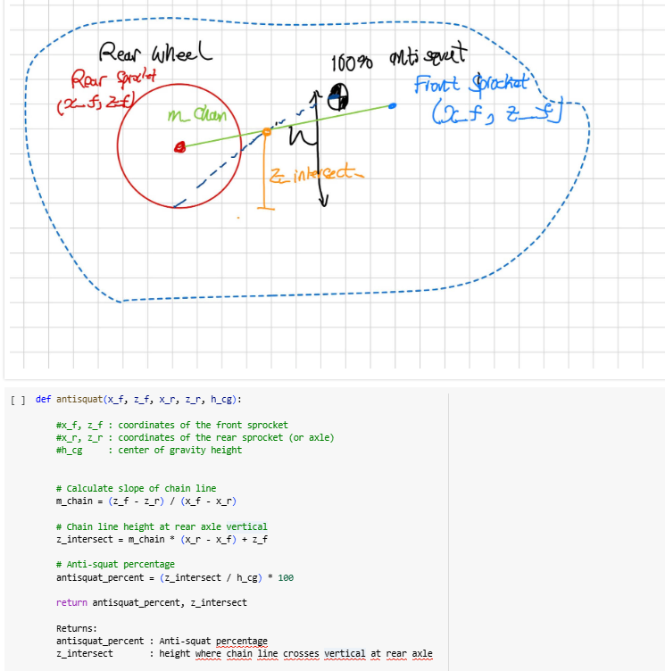
Anti-squat describes how much the rear suspension compresses under acceleration: too much and the bike loses traction, while too little hurts cornering efficiency. I built a Python calculator to determine our ideal anti-squat percentage and the corresponding jackshaft position, with the mount geometry designed to be easily adjusted during testing.
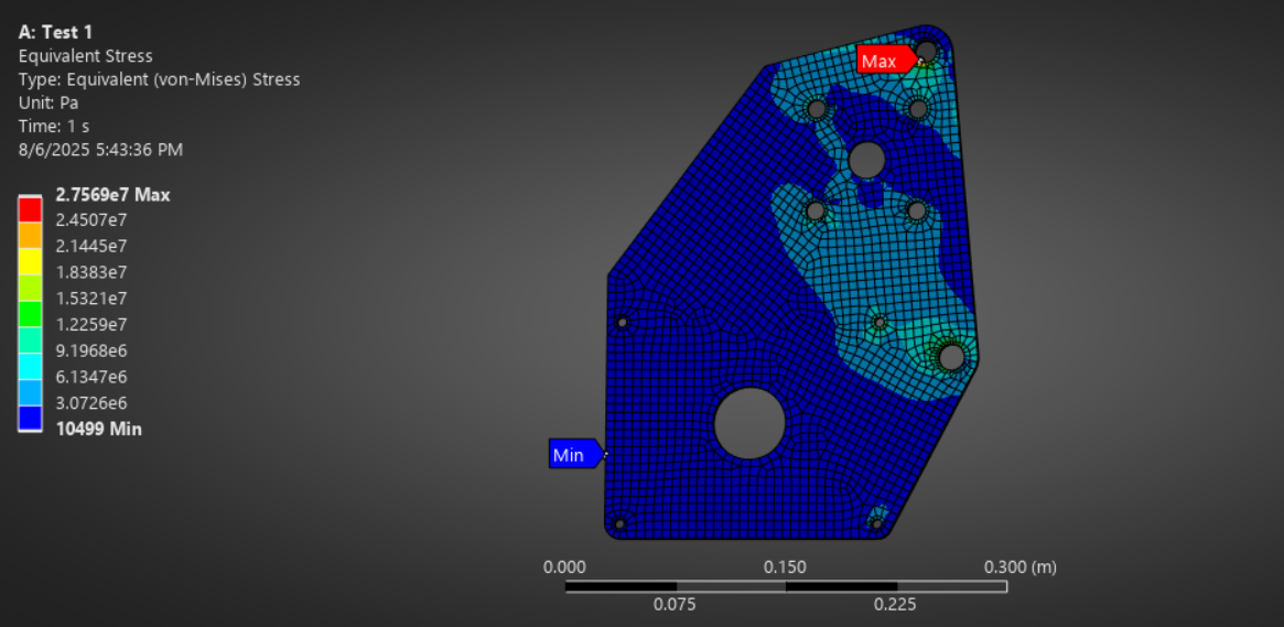
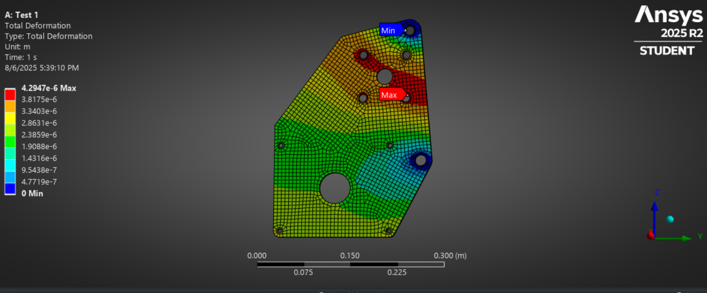
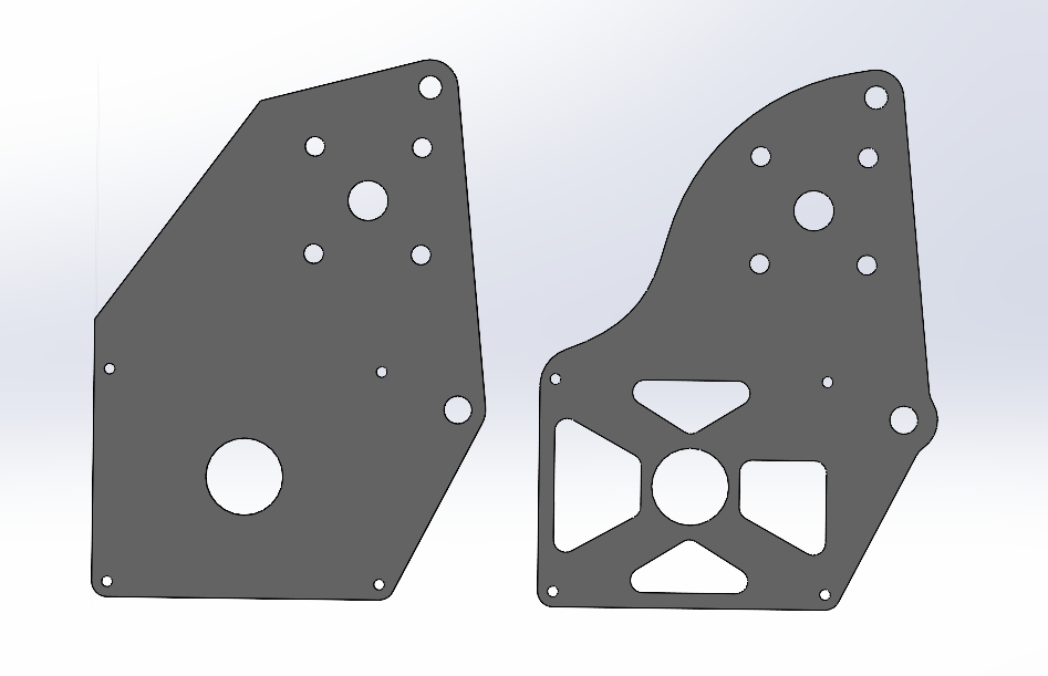
FEA in ANSYS Mechanical showed a peak Von Mises stress of 27.57 MPa against A36 steel's 250 MPa yield strength, giving a safety factor of ~9, with a maximum deformation of just 0.004 mm. I used those results to remove material in low-stress areas over a few iterations, achieving a 26% weight reduction while staying well within a safety factor of 3.
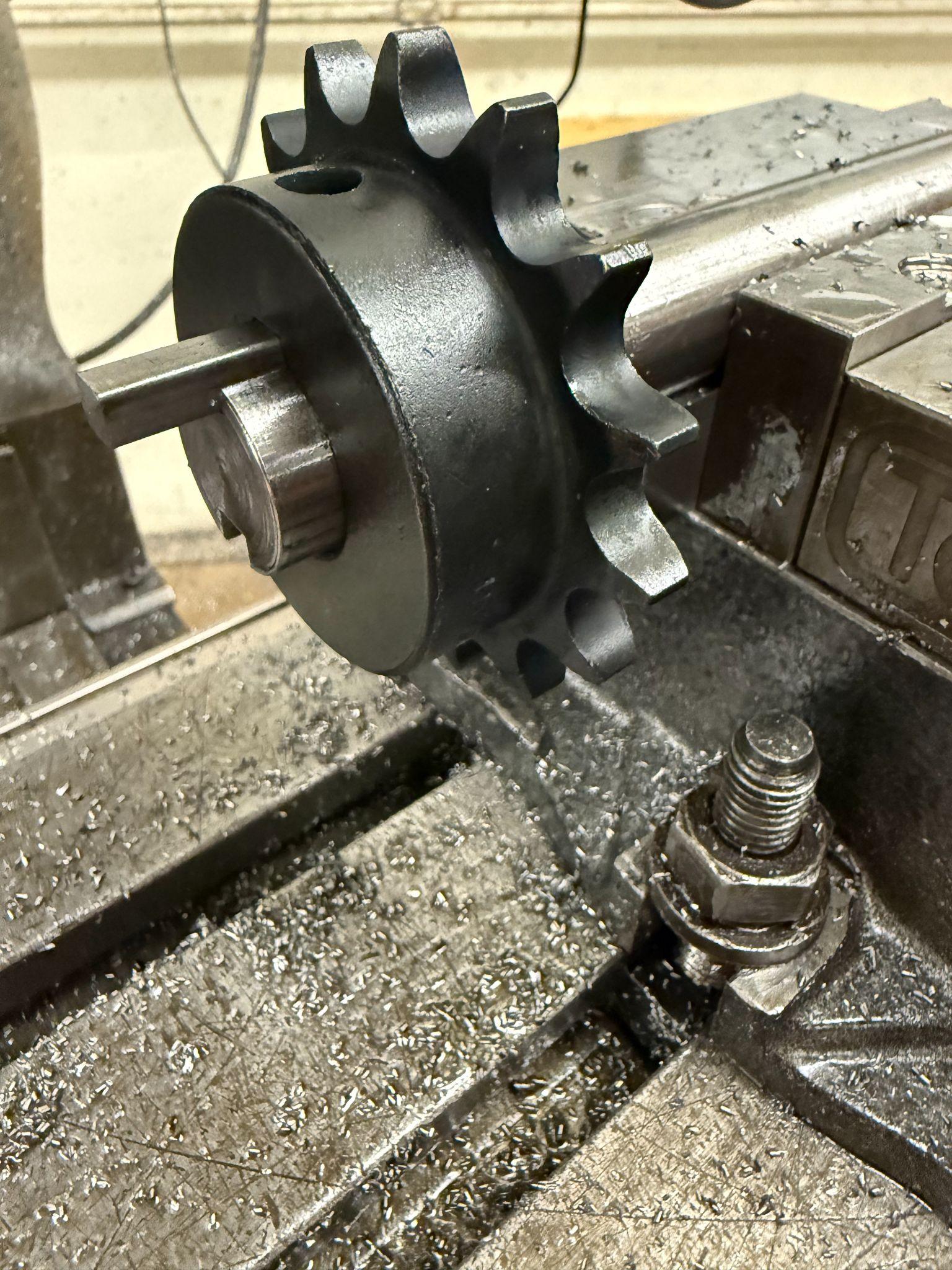
With the design finalized, it was time to build. I machined 6 unique components on a manual mill and manual lathe, holding tolerances within 0.005" throughout. The motor mounts were cut from ¼" A36 steel plate on our school's waterjet cutter, which kept per-part costs low and made it easy to quickly iterate on the geometry.
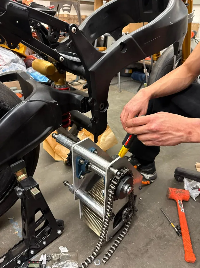
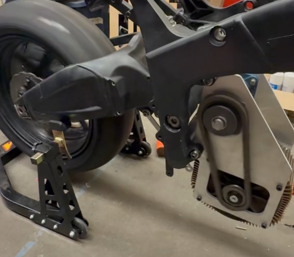
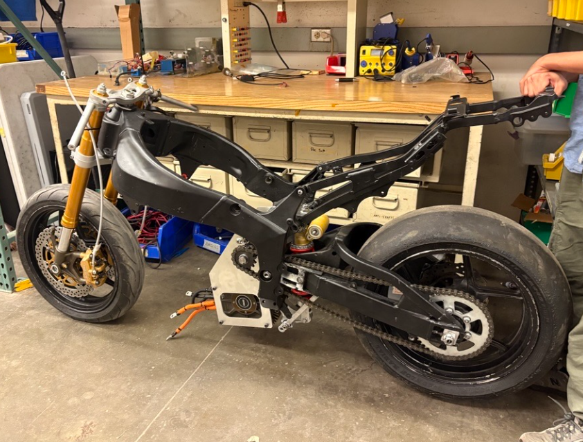
With all components in hand, the drivetrain came together without issue. Total material and COTS component costs came in under $300, and the first rolling test confirmed everything worked as designed: the bike moved under its own power for the first time.